Saturday, May 19, 2018

Project - Automated Water Control System

This project I done in year 2013 for a University student for his final year project for Bachelor of Engineering (Hons.) in Electrical and Electronic Engineering.
I did only the hardware part, no report writing.

This project is to monitor and record water level of over head tank while controlling of water pump to pump water if necessary. the system include security measures to stop pumping is sump tank is empty. also the system include LCD display which displays current status of system. recorded data is to be send to a PC for further analysis if necessary via a USB connection. 

The system include a microcontroller, ultrasonic range finder, an EEPROM, a Real Time Clock with Calendar and character LCD display.

Microchip Microcontroller PIC18F2550 was used as microcontroller in the system. The microcontroller include USB connectivity therefore it was selected among available chips in the market.

 
PIC18F2550


ultrasound ranger finder used in the project is SRF02. connectivity of the sensor is I2C. The sensor is responsible for measure distance upon request and provide the distance in either centimetres or inches. Accuracy of measurement is higher when compared with other similar range finders in the market. Also the advantage of using SRF02 is the process of measuring and calculating of range is off the processor.

SRF02 Ultrasonic Range Finder


The EEPROM used in the system is AT24C32 manufactured by Atmel. The chip include memory space of 32768bits arranged as 8bit registers of 4098. The water level logging required only 5 memory spaces ( MM DD(WL) ) . The program is written to logging in every 5 minutes. Therefore the chip is capable of holding 800 records spanning 66 hours and 30 minutes. This is sufficient enough to hold logging before connecting and downloading data to a PC. 

Real Time Clock used in the project is DS1307. The chip has clock and calender with leap year correction. Also the chip has back up power input. with connected back up power CR2032 button cell, the chip could continue to run clock for more than 10 years.


DS1307
The LCD display used in this project is 16 x 2 character LCD. This type of LCDs come with a LED back light in several colours. Therefore power requirement of the LCD is low. The data connectivity required 6 lines. 4 for data and 2 for control.

16 x 2 Character Display

A relay is used to switch water pump. And two electrodes were used to check water level of sump tank. if the water level drooped predefined level in sump tank the operation of water pump stopped, but it continue other functions.
Following is the schematic of system. Followed by PCB layout.
Schematic of System
PCB layout of system
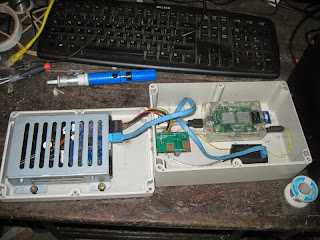
Following are the pictures taken during system testing.


Firmware for the system written using C language.

The Firmware Code : Water_Level_Meter.txt
LCD Driver library : flex_lcd.txt


මෙම ලිපියෙහි සිංහල පරිවර්තනය සඳහා පිවිසෙන ඉලෙක්ට්‍රොනික ලෝකය  

Friday, May 11, 2018

Project - PC Based Industrial Equipment Controller

This project I did for a university student in 2015 as his final year project for BEng(Hons) in Electrical and Electronic Engineering.

The project, PC based industry equipment controller is to monitor and control illumination lights and equipments remotely using a PC based software.
The project is to be used in a industry environment, where the factory expand to several buildings and away from monitoring station. controlling of illumination lights done individually or as cluster using a relay switch. Status of light bulb is checked by reading output pin register. status of motors such as voltage, current consumption and revolution is read using sensors.
in this project one light bulb and a motor is used to demonstrate.
The data to monitoring station was planed to send via 2.4 GHz digital transceiver unit. because the factoring buildings and monitoring station is far away, and it is not possible to plant wires to communicate.
Following is the block diagram of the system,
Block Diagram of System
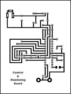
Following is the schematic diagrams of Factory side unit and Monitoring side unit

Schematic Control and Monitoring Side

Factory Side Schematic
Factory side unit reads current consumption of motor using hall effect current sensor. Voltage is measured using resistor divider. and speed of motor measured using slotted disk attached to motor shaft and slotted op-to coupler. these data is processed and calculate to get useful information, then send to Monitoring side along with status of light bulb using nRF24L01+ digital transceiver.
On the monitoring side the microcontroller read bulb state to be set from PC and waits for incoming packets from Factory side nRF24L01+ transceiver. nRF24L01+ transceiver have ability of sending data with acknowledge signal to received data packets. 
also the nRF24L01+ transceiver configured as receiver have ability to receive form 6, nRF24L01+ transceivers configure as transmuters. therefore it is possible to have more than 1 factory side circuits. upon reception of motor and light status, monitoring side board send data to software on PC.


Above are the PCB drawings of units.
Following figures show the solders PCBs ready to program. 

Monitoring Side Unit
 The Black colour PCB in top centre of picture is nRF24L01+ Transceiver this unit capable of establishing radio wave link up to 100 meters with patch antenna formed using Copper paths. the unit could configure as either transmitter or receiver in program. communication between two units are secure using a security ID. USB port on the right side is used to connect to PC to send data. 


This board is on factory side. the chip on the centre is the Microchip microcontroller. the unit on top left side is current sensor. The sensor measure magnetic field induced when current passes true to measure using hall magnetic sensor. the unit out put analogue signal proportional to the current pass through. The relay, on bottom right side used to control Light bulbs.


The picture above show instance of testing system. I also have done the project report for the particular student. 

Following are the program Codes.

Factory Side Program Code : Factory_side.txt
Control Room Side Program Code : Control_Room.txt
nRF24L01+ Library : nRF24L01P.txt

PC Based Industrial Equipment Controller Project Report

මෙම ලිපියෙහි සිංහල පරිවර්තනය සඳහා පිවිසෙන ඉලෙක්ට්‍රොනික ලෝකය  

Wednesday, May 9, 2018

Raspberry Pi - Hardware

In this post I expect to discuss regarding hardware of Raspberry Pi. In a previous post I have introduced Raspberry Pi to you.
Even though Raspberry Pi small similar in size to Arduino Uno, It is not a Microcontroller circuit. Raspberry Pi is unique that, with use of it one could do almost all the tasks any computer could do even the size is smaller.
when consider a computer hardware there are several components. the computer consist of a Micro processor, two chips Northridge and South-bridge and few supporting chips act as level convertors and interfaces such as USB, serial ports and parallel ports. when consider structure, Northridge is connected to Microprocessor and south-bridge connected to micro processor through north-bridge. South-bridge has relatively low speed than North-bridge. The graphic processor and RAM memory is connected to North-bridge and PCI, USB, Serial ports and BIOS are connected to South-bridge.
In Raspberry Pi all these components are included in a single chip. Therefore this chip is called System on Chip. Raspberry Pi inventor Mr. Eben Upton being an engineer of Broadcom and due to the agreement with the company, Raspberry Pi was included a Broadcom SOC. This chip custom made for Raspberry Pi including Micro processor, Graphic Processor and USB, GPIO,I2C and SPI interfaces.


Broadcom BCM2837 SOC Chip.
In addition to SOC, Raspberry Pi board consist of RAM Memory,Ethernet interface chip and Voltage Regulator. Raspberry Pi users BCM2835, BMC2836, BMC2837 depending on model.

Raspberry Pi concept Board 2006

This module was made by Eben Upton to test and experiment Raspberry Pi concept. this model was assembled on a veroboard on 2006. Has a Atmel ATmega644 microcontroller running with 22.1MHz clock. It also consist of 512K SRAM (Static-RAM) and it was used to store general program data and video data. If you look in the bellow picture, left most chip is the Atmel microcontroller and next to it is the SRAM chip. 19 pins out of 32 I/O pins in Atmel chip was used to send data to SRAM chip. A conventional Television was used as output video monitor for this device has resolution of 320 x 240. You could watch the first experiment from here. The video was done by Liz Upton, wife of Eben Upton.
Video data on SRAM was send to Television pixel by pixel through 74HC series 3 buffers to 3 ADC chips to generate video signal. time duration between vertical and horizontal blanking of video is used to process non video data.


Raspberry Pi Concept 2006 Edition 

Raspberry Pi USB Prototype Board

After Establishing Raspberry Pi foundation, on May 2011 The Raspberry Pi prototype board was developed. this was small printed board type device. the unit had HDMI port to connect to screen and a USB drive on other end. Also the unit had on board camera. There were not much details on device on Internet. However people at Broadcom call the device 'MicroDB'.

Raspberry Pi Alpha Board

In August 2011, Raspberry Pi foundation had made a 'Raspberry Pi Alpha Board' It was not made to sell, rather to check and debug.

Raspberry Pi Beta Production Board
the foundation design 'Raspberry Pi Production Board'. And produced 100 printed circuit boards of this type. but only solder 10 boards. On January 1st 2012 they put soldered 10 devices on eBay on auction. intention of auction was to gather money to the foundation. the action was a success. the highest bid was GBP3500 and lowest was GBP930.
following is auction number 8. Picture was taken from blog of Paul Maunders. Follow the link to his blog post.

Raspberry Pi Beta Production Board.
https://www.pyrosoft.co.uk/blog/2012/01/13/raspberry-pi-8-first-photoshoot/
Raspberry Pi 1st Production Board

on 29th February 2012, new era began with realease of Raspberry Pi 1st production Board.this model is similer to Raspberry Pi Beta Production Board. But the RCA port used to connect to TV was yellow colour and the SD card slot was little bit shifted inward the board. 10,000 board was made and sold. The board was Assembled in China. 

Raspberry Pi Full Production Board aka Raspberry Pi 1 Model B

Raspberry Pi 1 Model B is much similar to Raspberry Pi Beta Production Board and Raspberry Pi 1st Production Board. But there are slight differences. The board was released on April 2012. And was assembled in China. Distribution and sales was done through Farnel (Now Element14). 
after September 2012 the board was began to manufacture in Sony Manufacturing Plant at Wales, UK. Liz Upton wrote about the decition in foundation web site. 

"If you’ve been following us for a while, you’ll remember the time last year when we had to make the decision to manufacture the Raspberry Pi in China. The Raspberry Pi is a British enterprise, and as well as improving things in the computing industry’s future here by educating kids, we wanted to improve things in the present too, by actually doing our manufacture here in the UK."

Today every Raspberry Pi sold in United Kingdom is made in UK. and for the rest of the World, Raspberry Pi is manufacture in China. And Distribution is done through Element14.

Raspberry Pi 1 Model A

This model was released in February 2013. Much similar to Model B, but didn't include Ethernet port to connect to Network.

Raspberry Pi Computer Module

This model was released in April 2014. The SOC chip and RAM memory and eMMC Flash memory only include in this module. the size and shape similar to RAM card of Laptop computer. connecting interface too. Following picture show the module. The operating system and data is stored in eMMC flash memory instead of SD card in previous models.

Raspberry Pi Computer Module
http://elinux.org/images/8/83/Compute-module.png

Raspberry Pi 1 Model B+

On 14th July 2014, The Raspberry Pi foundation released new advanced model of Raspberry Pi 1 Model B. It was called Raspberry Pi Model B+. This model similar To Raspberry Pi 1 Model B in size and SOC chip. But new model contain 4 USB ports instead of 2. Therefore the unit could plug additional 2 USB devices addition to Key Board and Mouse. And instead of SD card the unit include MicroSD card. Also count of GPIO pins has increased from 26 to 40. 

Raspberry Pi 2 Model B

On Februarry 2015 new advanced model was introduced. Raspberry Pi 2 Model B had new fast quad core SOC chip. Also the RAM memory was increased to 1GB. Rest of features were remain same as RPi 1 Model B+. 


Raspberry Pi 3 Model B

After 4 years of release of first RPi, February 29, 2016 all new Raspberry Pi was released. The Raspberry Pi 3 Model B has more powerful 1.2GHz Quard Core 64bit SOC chip. This model has WiFi and Bluetooh conncetivity. But Ethernet port also remain. with this released RPi alllowed to run 64bit operating systems.


Raspberry Pi Zero and Raspberry Pi Zero W

In addition to Credit card size Raspberry Pi, the foundation released Raspberry Pi Zero. Smaller version of Raspberry Pi on November 2015. On 28th February 2017, 5th Birthday of Raspberry Pi foundation introduced Raspberry Pi Zero W. which is similar to Raspberry Pi Zero with on addition of Wi-Fi. Due to the demand one house in UK could order only one device.

Raspberry Pi Computer Module 3 and 3 Lite

These models were released on January 2017. Much similar to Raspberry Pi Computer Module. But have SOC chip and RAM memory same as RPi 3 Model B. But instead of MicroSD card in RPi 3 Model B, the unit has 4GB eMMC chip. but Lite version of this release do not have 4GB eMMC Flash.

we have talked about history of Raspberry Pi. We shall now consider important component SOC chip now.
SOC or System On Chip is made by including all the important components such as Micro processor, RAM memory, Graphic processor and etc. combining in to one chip. Devices such as Mobile Phones, Television and printers are also include SOC chips.
The SOC on Raspberry Pi include Micro Processor, Graphic Processor and Input/Output port. BCM2835, BCM2836 and BCM2837 are the part numbers of SOC included in Raspberry Pi so far. How ever these parts numbers are only available and included in Raspberry Pi only.

BCM2835

This chip included in RPi 1 Model A, RPi 1 Model B, RPi Computer Module 1, RPi Zero and RPi Zero W. The chip include single-core ARM1176JZF-S. It is a 32bit micro processor by ARM Holding of UK. It has ARM11 family with ARMv6 architecture. And Broadcom VideoCore IV graphic processor. Clock speed the SOC chip runs varies from model to model. RPi 1 Model A, RPi 1 Model B, RPi Computer Module 1 runs on 700MHz speed while RPi Zero and RPi Zero W runs on 1GHz speed. 
Famous Apple iPhones are also include SOCs with ARM micro processors.

BMC2836

This SOC include only in RPi 2 Model B. It run by 700MHz clock speed. include 32bit Quard-core ARM Cortex-A7 Micro Processor.

BMC2837

The RPi 2 Model B, RPi 3 Model B and RPi Computer Module 3, 3 Lite modules made after October, 2016 include this SOCs. This include Quard-core ARM Cortex-A53 Micro processor. ARM Cortex-A53 has architecture of ARMv8-A. The clock rate on RPi 2 Model B is 900MHz and RPi 3 Model B and RPi Computer Module has 1.2GHz speed.

In addition to SOC Raspberry Pi include many other components. For example the switch mode power supply to reduce voltage from 5V to 3.3V and Ethernet controller chip. 

This conclude blog post regarding Raspberry Pi hardware. Next post is expected to be regarding the operating systems used in Raspberry Pi.


References :

1. https://en.wikipedia.org/wiki/System_on_a_chip 
2. https://en.wikipedia.org/wiki/Northbridge_(computing) 
3. http://elinux.org/RPi_HardwareHistory
4. https://www.raspberrypi.org/blog/raspberry-pi-2006-edition/
5. https://www.pyrosoft.co.uk/blog/2012/01/13/raspberry-pi-8-first-photoshoot/

මෙම ලිපියෙහි සිංහල පරිවර්තනය සඳහා පිවිසෙන ඉලෙක්ට්‍රොනික ලෝකය  

Tuesday, May 8, 2018

Raspberry Pi - Introduction

When you heard word 'Pi' many come to mind popular Greek letter π. It represent ratio between circumference and radios between a circle. which is truly remarkable number.some might remember popular dessert. the dessert that made of pastry dough casing that covers or completely contain a filling of various sweets.
the pi which contain raspberry is called Raspberry Pi


A Raspberry Pi


Now you might be wondering why this blogger talk about desserts. and might be wondering you came to wrong blog. No you are in correct blog. In ever changing world the image in your mind when you heard 'Raspberry Pi' has changed about 5 years ago. If you type in on Google the word 'Raspberry Pi' you will get following picture or a picture smilier to this.


The Raspberry Pi
What is this Raspberry Pi truly ?

Raspberry Pi is a credit card or ATM card size small computer. Even though this device is small in size tasks this device could perform is not small.like typical computer, the Raspberry Pi could be connected with a computer monitor, a key board and mouse. also it could be program to run a small program. It could configure to run services such as MySQL server, Apache web server etc. Also the operating system include common applications such as Word processor, Spread sheet and web browser to browse Internet. the unit contain a powerful video processor to play high definition video.

who invent this Raspberry Pi?

around 2006 number of student to Computer science department and their knowledge in computer science of Cambridge university of UK was declining. As a solution, Eben Upton, Rob Mullins, Jack Lang and Alan Mycroft who served in Computer Science Lab of Cambridge University of UK, think of producing a small, low cost computers for teaching and learning. The team come up with few designs but eventually have to give up, due to non availability of low power microcontrollers and high manufacturing cost.
Later the team, teamed up with CEO of Norcott Technologies, Pete Lomas and Co-inventor of Computer game 'Elit', David Barben to form Non profitable organization, 'Raspberry Pi Foundation'.
after three years the foundation come up with the initial design of Raspberry Pi. After initial tests and corrections, The organization Launched and began selling of 'Raspberry Pi Model A' on February 29th 2012 6 O'clock in the morning of Greenwich Mean Time. after two years the sales count of unit exceeds 2 Millions.
Since then the Raspberry Pi foundation has launched 11 models and according to the magazine 'MagPi' published, total sales count exceeds 12.5 millions.

The released models are,

Raspberry Pi 1 Model A
Raspberry Pi 1 Model A+
Raspberry Pi 1 Model B
Raspberry Pi 1 Model B+
Raspberry Pi 2 Model B
Raspberry Pi 3 Model B
Raspberry Pi ZERO
Raspberry Pi ZERO W
Raspberry Pi Computer Module 1
Raspberry Pi Computer Module 3
Raspberry Pi Computer Module 3 Lite

According to the MagPi presentage of sales as follows,


 Source - https://www.raspberrypi.org/magpi/raspberry-pi-sales/
We shall discuss the hardware and software of Raspberry Pi in next posts. Later the projects could be done using Raspberry Pi.

Sources - 

1. https://www.raspberrypi.org/
2. https://en.wikipedia.org/wiki/Raspberry_Pi
3. https://en.wikipedia.org/wiki/Raspberry_Pi_Foundation
4. https://www.raspberrypi.org/magpi/raspberry-pi-sales/

මෙම ලිපියෙහි සිංහල පරිවර්තනය සඳහා පිවිසෙන ඉලෙක්ට්‍රොනික ලෝකය  

Tuesday, June 14, 2016

Automatic Water Pump Controller

Introduction
We face many problems when we use water pump every day life. Water spill unknowing of water level at the time of pump operation. run out of water when doing some thing such as taking bath. the objectives of this project is to find solution of problems associate with filling of overhead water tanks using electronic pump. Also knowing of water level of water tank. stop operation of pump when water get contaminated with such as mud.

Methodology
A micro-controller used as controller of the system. To measure water level a water level sensor based on electric conduction of water was used. these sensors were fixed on , lowest, highest and mid level of the tank. To sense impurities of water, a sensor to measure transparency of water is fixed at the entry point of water from the well. This sensor consist of LED bulb and photo-diode allowing water flow in between. also there is a water sensor about 6 inch above the water entry point of well, to sense presence of water.
A relay used to operate water pump. Water level, status of water pump and quality of water is displayed on LCD display.

The Circuit

Automatic water pump and water level display


The Circuit was drawn using CorelDRAW software and printed circuit board was fabricated using screen printing method and Ferric Chloride solution to dissolve exposed copper. 


Printed Circuit Board layout


මෙම ලිපියෙහි සිංහල පරිවර්තනය සඳහා පිවිසෙන ඉලෙක්ට්‍රොනික ලෝකය  
 

Story of Electricity - 1

Electricity and Electric operation equipment have become essential part of our every day life. Today, even few minutes of power cut have major effect on our life. we feel like we have gone to stone age all the sudden.

But thousands of year ago the electricity bring only destruction to human world. The lightning, electricity to early human caused making forest fire, destruction to trees, blogs of stones some times coursed lost of life to human as well as animals only. They might not have slightest imagination that the same day future the electricity become a slave. 

Before knowing the properties of electricity, the early human known about electric eel and lighting have some thing common. According to the Egyptian papyrus dating back 2750BC, the electric eel was known as 'Thunderers of the Nile'

Amber is fossilized tree resin made by nature solidified over millions of years. at around 6th century BC The people lived in Mediterranean sea coastal areas trade amber. and also made jewelry out of amber. they have observed that when the amber was rubbed against wool, smaller lighter things such as smaller feathers get attracted. 

One person try to explain this phenomenon is Thales. He lived in Miletus, modern day Turkey. He is the one of first Greek philosopher. He was coined as 'Father of Greek philosophy' by Aristotle. Also he is named as 'Father of Science'.
The force of attraction by the Amber is explained by the Thales as magnetic force. He explained it further as magnetic force by friction.

After the Thales, amber and the magnetic force by the amber was forgotten to the world of science. the experiments about the amber and the forces by amber began at around 1600AD after 2200 years.

මෙම ලිපියෙහි සිංහල පරිවර්තනය සඳහා පිවිසෙන ඉලෙක්ට්‍රොනික ලෝකය  

Monday, April 18, 2016

Network Attached Storage (NAS)

We all work with computers. So the files we working, worked on, Pictures took, movies, software and other, all are stored on our computer. most of us have more than 75% of our hard disk filled. and office files, files requested by others are stored on our pen drive. we continue to work like that until computer started to give out notifications and warnings. only then we realized we should make some space in our computer. only option we have is to copy to external hard drive or delete some we collect dearly. some times the computer operation system get crashed due to some hardware or software malfunction or virus infection, then we lost every thing.
In offices they use a separate computer to store files called file server. file servers usually have fast processor, large memory and large capacity hard drive. the computer connect and access by others through computer. These sort of files servers are expensive and required high maintenance cost.
It is not economical to use expensive file servers for small office or a house. However there is a solution for that. Those are called Network Attached Storage or NAS in short. Both have similarities and differences as well.
when we take similarities both do same task, storing Files and provide access to. With advance technology both provide similar access speed.
Difference is the way providing access to files. In file servers connection between hard disk and network is done using software. Computer is operated on Operating system and another software operate on top of operation system establish the connection. But NAS on the other hand, have comparatively smaller software stored on a memory and and the program is called firmware. Due to the use of operating system File servers essentially have fast processor and large memory and fast access hard disk. therefore File servers use considerable electric power. On the other hand NAS need less electricity.


A NAS manufactured by NETGEAR(from Wikipedia)
Shall we talk about the NAS device made by me. The NAS was done by me using a Raspberry Pi. What is this Raspberry Pi ? Raspberry Pi is a small computer. Basically it has a slot to plug in a monitor, USB ports to connect a Key Board and a Mouse. Raspberry Pi was design primarily to work with a Linux based operation system known as Raspberian. Raspberry Pi has several version newest ones could operate by reduced version of  Microsoft Windows 10 operation system.
The Raspberry Pi, I used for NAS is a bit older version called Raspberry Pi model B. This Raspberry Pi has, HDMI out put and a Composite video out put, where newer versions have on only a HDMI port. Also the device consist with two USB ports and 26 pins to be used as a General purpose Input Output (GPIO). A SD Memory card used to input operating system to operate on.


 Raspberry Pi 1 Model B

Following are the list of things to assemble NAS.

Raspberry Pi 1 Model B with 8GB SD card
500GB SATA Hard Disk
SATA to USB convertor
5V Power Regulator
Plastic Box

Aditionally a cable with a micro USB cable to supply 5V power to Raspberry Pi and small cable with RJ45 jack and a RJ45 outlet was used.

All the Components used.

First a slot was cut to hold RJ45 outlet on one side of plastic box. And the outlet was fixed to that slot.


Also a round hall to fix 5V regulator......


The SD card was insert to Memory card slot of Raspberry Pi after copying operation system . The operation system used is Raspbian Wheezy edition of LinuxAs I was expecting to configure the NAS remotely a remote desktop sharing software was installed using following command.

sudo apt-get install xrdp 

This 'xrdp' software allow to access desktop of Raspberry Pi remotely using Remote Desktop Software over the network

Box was closed after fixing the hard disk firmly on the bottom of box using nuts and bolt and metal frame and wiring.


After powering up the device, 'Remote Desktop' software in Microsoft windows was used to log in to Raspberry Pi, to do rest of configurations.


Installing SAMBA software

sudo apt-get install samba
sudo apt-get install samba-common-bin

SAMBA is the access pint to the files on drive through internet. another word SAMBA is the file server software. with above two comands we have finished installing SAMBA on to Raspberry Pi.
Now we had to format the hard drive. 
I was using the same drive as external hard drive to my computer using SATA-USB converter for quite some times. therefore the file system already on the drive is NTFS. 
But, as the Raspberry Pi operating system based on Linux, it is better to use ext4 file system for the drive. one disadvantage of convertion is, in case Raspberry Pi is not working, I will not be able to plug the drive as external hard drive to computer to get access to files. 
for making new partion the command 'fdisk' used.


sudo fdisk /dev/sda


fist of all had to remove NTFS file format partion already in the drive. for removal used key 'd' to delete all existing partions. after that use key 'w' to save changes. this will also exit the utility program. again use same command to open software to create new partion. 
use key 'n' to create new partion. then use key 'p' to make new primary partion. press 'Enter' key to select default value as staring and ending cluster for new partition, if to use full disk. use key 'w' to save and exit utility software. 
now it is time to format new partion. following command used to format newly creation.

sudo mkfs.ext4 -L DATA /dev/sda1

the command format the partion in ext4 format and same time set disk label as 'DATA'.
At same time we make a folder named '/data'. and mount the new partion 'DATA' on to the folder. in order to mount drive at startup, we are adding following command to 'fstab' file in 'etc' folder.

LABEL=DATA /data ext4 defaults 0 2

Now have to configure SAMBA server, to share mounted folder with outside world. 
For that we have to goto instillation folded of SAMBA. Following command achieve task.

cd /etc/samba

All the configurations of SAMBA is on the file called 'smb.conf' on that folder. To open file to edit, following command is used. 

sudo nano smb.conf

This command allow to edit 'smb.conf' file. First go down the code list and change '# wins suport=no' under [global] as following.

wins suport=yes


go further down and remove '#' at the front of 'name resolve order' to active configuration. This allow the network to identify our drive. now we are almost finished the configuration. now it is time to identify mounted folder to SAMBA server as shared folder.
Go further down and find section 'share definition'. Add following after [homes].
 
[pi_share]

  path=/data
  public=yes
  browseable=yes
  create mask=0777
  directory mask=0777
  only guest=yes
  read only=no

This conclude configuration, save the file and exit.Restart the Raspberry Pi.
Goto the computer and look under, network folder. it show some thing similar to this.


I thought every thing is finished, but it was not. Cover I smell something burning. Hard disk got heated up due to no ventilation. So cooling fan of old DELL power supply was fixed in. and small holes were made both sides to support air circulation.


Now everything all right. But the fan produce loud sound when operate. The DELL power supply has a resistive temperature sensor. I make a circuit to increase speed of fan depending on the temperature. The sensor was fixed on to body of hard disk.


Now every thing is ready. I copy all the movies on my computer to NAS....

What are the advantages and disadvantages of Raspberry Pi NAS  device ?
One advantages are low cost and low power requirement. If decide to buy every thing, it will be cost around Rs. 20,000 to Rs. 25,000. Power requirement varied between 10W to 15W. It will required around 7.2KWh to 10.8KWh to operate for month around the clock. It is very less compared to 360KWh required by File server with 500W power supply.

The disadvantage is the low data transfer speed. Normally the data transfer speed vary between 6Mbps to 1Mbps. But I think it is fair for use in a house.


මෙම ලිපියෙහි සිංහල පරිවර්තනය සඳහා පිවිසෙන ඉලෙක්ට්‍රොනික ලෝකය