The project, PC based industry equipment controller is to monitor and control illumination lights and equipments remotely using a PC based software.
The project is to be used in a industry environment, where the factory expand to several buildings and away from monitoring station. controlling of illumination lights done individually or as cluster using a relay switch. Status of light bulb is checked by reading output pin register. status of motors such as voltage, current consumption and revolution is read using sensors.
in this project one light bulb and a motor is used to demonstrate.
The data to monitoring station was planed to send via 2.4 GHz digital transceiver unit. because the factoring buildings and monitoring station is far away, and it is not possible to plant wires to communicate.
Following is the block diagram of the system,
 |
| Block Diagram of System |
 |
| Schematic Control and Monitoring Side |
 |
| Factory Side Schematic |
On the monitoring side the microcontroller read bulb state to be set from PC and waits for incoming packets from Factory side nRF24L01+ transceiver. nRF24L01+ transceiver have ability of sending data with acknowledge signal to received data packets.
also the nRF24L01+ transceiver configured as receiver have ability to receive form 6, nRF24L01+ transceivers configure as transmuters. therefore it is possible to have more than 1 factory side circuits. upon reception of motor and light status, monitoring side board send data to software on PC.
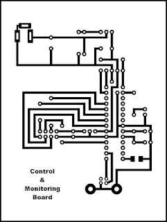
Above are the PCB drawings of units.
Following figures show the solders PCBs ready to program.
 | |||||
| Monitoring Side Unit |
This board is on factory side. the chip on the centre is the Microchip microcontroller. the unit on top left side is current sensor. The sensor measure magnetic field induced when current passes true to measure using hall magnetic sensor. the unit out put analogue signal proportional to the current pass through. The relay, on bottom right side used to control Light bulbs.
The picture above show instance of testing system. I also have done the project report for the particular student.
Following are the program Codes.
Factory Side Program Code : Factory_side.txt
Control Room Side Program Code : Control_Room.txt
nRF24L01+ Library : nRF24L01P.txt
PC Based Industrial Equipment Controller Project Report
මෙම ලිපියෙහි සිංහල පරිවර්තනය සඳහා පිවිසෙන ඉලෙක්ට්රොනික ලෝකය


No comments:
Post a Comment